A corrugated plastic dunnage system should be designed around the part, not around a generic box size. Automotive components vary in geometry, weight, exposed finishes, connectors and the way operators load them. These differences determine where packaging may touch a part, how it should be located, how many units can fit in a container and whether the structure needs dividers, shaped inserts, layer pads or another support. The outer box or tote matters, but it is only one part of the system. A useful design brief also describes the route: line-side handling, warehouse storage, transport, unloading and, where relevant, empty return. This guide sets out the decisions to review before a drawing or sample is approved. It is a design framework, not a universal material specification.
Start With the Part, Not the Box
Starting with a 600 × 400 container and a fixed sheet thickness can constrain the design before the protection problem is understood. First collect the actual part dimensions, shape, mass, required quantity, sensitive surfaces and handling method. Confirm whether the buyer already has a standard tote or pallet footprint; if so, record its usable internal dimensions rather than relying on the outside size. Only then decide which combination of outer container, cell layout, locating insert and support panel is appropriate.
This sequence separates a fixed logistics constraint from an assumed packaging answer and exposes unresolved contact or removal issues early.
Key Dunnage Design Inputs
| Design Input | Why It Matters |
|---|---|
| Part geometry | Determines the cell shape, orientation and locating structure. |
| Part weight | Influences support placement, packed weight and handling checks. |
| Allowed contact points | Helps keep packaging away from sensitive or functional surfaces. |
| Quantity per container | Sets the layout challenge and affects access and total load. |
| Loading direction | Changes clearance, hand access and removal sequence. |
| Handling and return route | Influences durability, inspection and empty-pack requirements. |
Review Part Geometry and Orientation
Record overall length, width and height, then identify projections, curved faces, sharp areas and features that cannot carry weight. A dimensioned drawing should be checked against a physical part or representative sample when possible: a bounding rectangle rarely explains how an irregular component will sit inside a cell. For a heavy or asymmetric part, its center of gravity can affect how it rests and how an operator grips it.
Try the intended loading orientation before fixing compartment dimensions. Turning a part can change pieces per layer, exposed contact surfaces and removal clearance. Where assembly-line sequence controls orientation, pack density must respect it.
Identify Safe Contact Points
Protective packaging cannot press indiscriminately against a component. Identify the surfaces that may support or locate the part and those that must remain clear. Cosmetic trim, painted or machined faces, lenses, electrical contacts and fragile connectors may need no-contact zones or a separately reviewed interface. A lamp housing, for example, may have robust mounting features beside a visible lens; a metal component may have a machined face that should not rub against a divider edge. These are general design examples, not descriptions of a specific customer project.
Mark contact zones on a drawing, then check behavior during lifting, stacking or vibration. A snug cell is not automatically safe: pressure at the wrong point can be worse than controlled clearance. Review contact conditions with the buyer before finalizing the design.
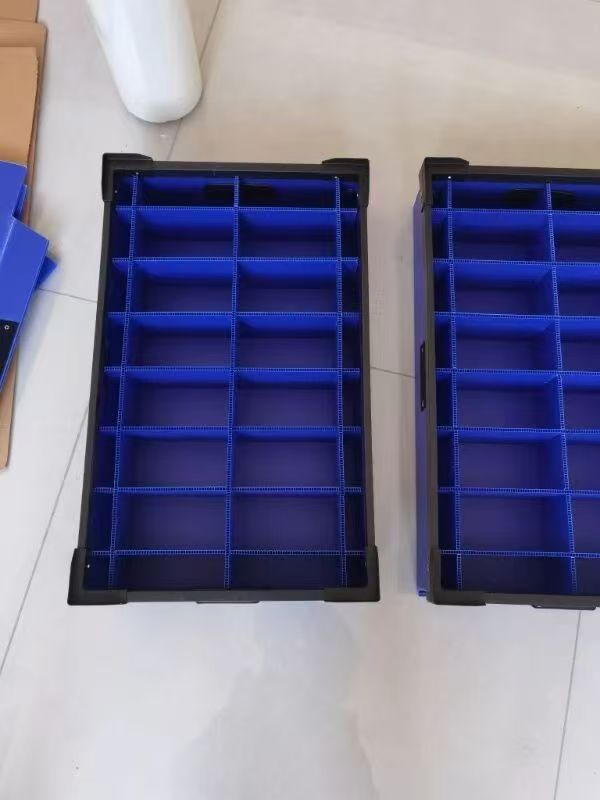
Define Quantity and Pack Density
“Pack 20 parts” is a starting requirement, not a complete layout. Confirm the quantity per container, orientation of each part, clearance between adjacent components, usable container dimensions, total packed weight and access for loading. If parts are placed in layers, determine what separates the layers and where their weight is transferred. Check whether the first part can be removed without displacing the rest.
Higher pack density is not automatically better. A tighter layout can reduce clearance, hinder grasping or create contact during insertion. Compare layouts against the loading sequence and transport route; usable quantity may be lower than the largest drawn quantity.
Choose the Right Internal Structure
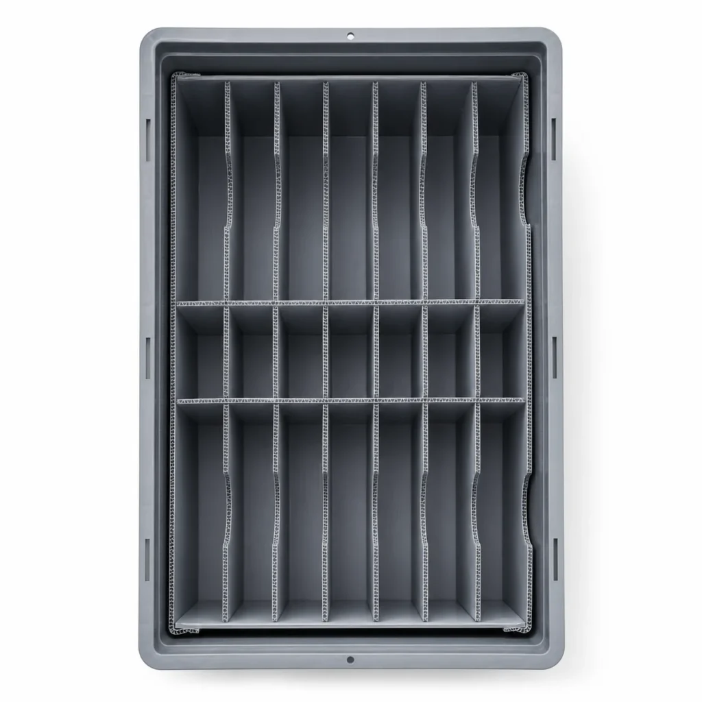
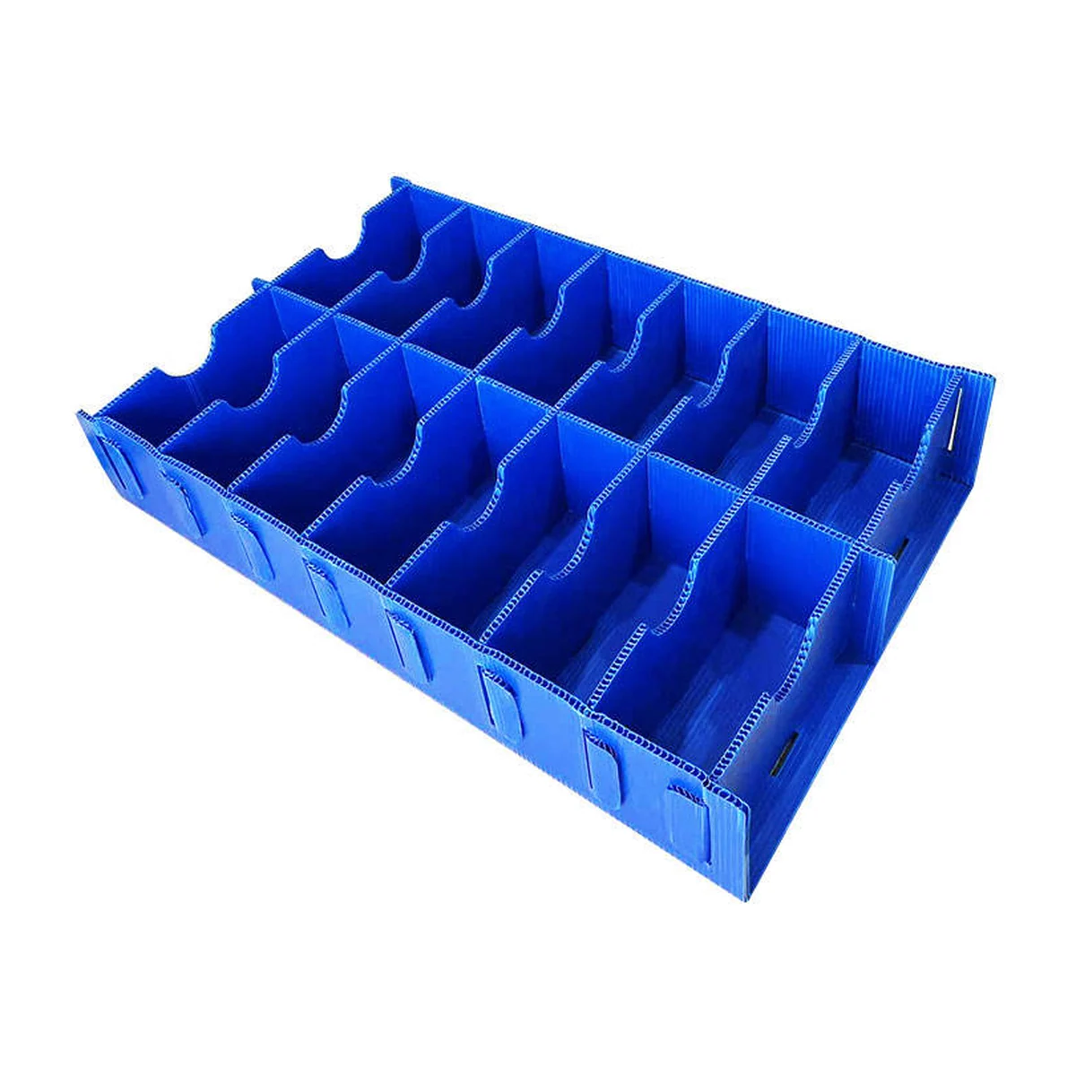
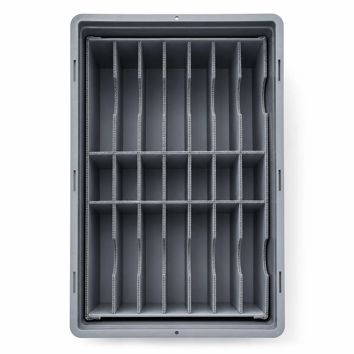
Different elements perform different jobs. Slotted dividers and inserts can separate parts into cells or provide local support. Layer pads separate tiers and can help distribute load through the pack. Support panels may reinforce a selected area. Dunnage is the coordinated locating and protective system: it may combine these elements to control part position, contact and movement inside an outer container. A divider is therefore one possible component of a dunnage design, not a synonym for the complete system.
The selected structure should be simple enough to assemble, load, inspect and replace as required. Review slot depth, edge exposure, attachment points and the possibility that a loose insert shifts during handling. For available product configurations, see the corrugated plastic dunnage product page.
Select Material Thickness and GSM
Thickness alone does not determine the strength of a PP corrugated structure. GSM describes sheet mass per unit area; it does not, by itself, specify stiffness or load capacity either. Two sheets of the same thickness may behave differently because of GSM, polypropylene formulation, filler ratio where relevant, rib geometry and orientation. Panel span, slot pattern and the direction of applied force also affect the finished assembly. Temperature and the expected load should be included in the review.
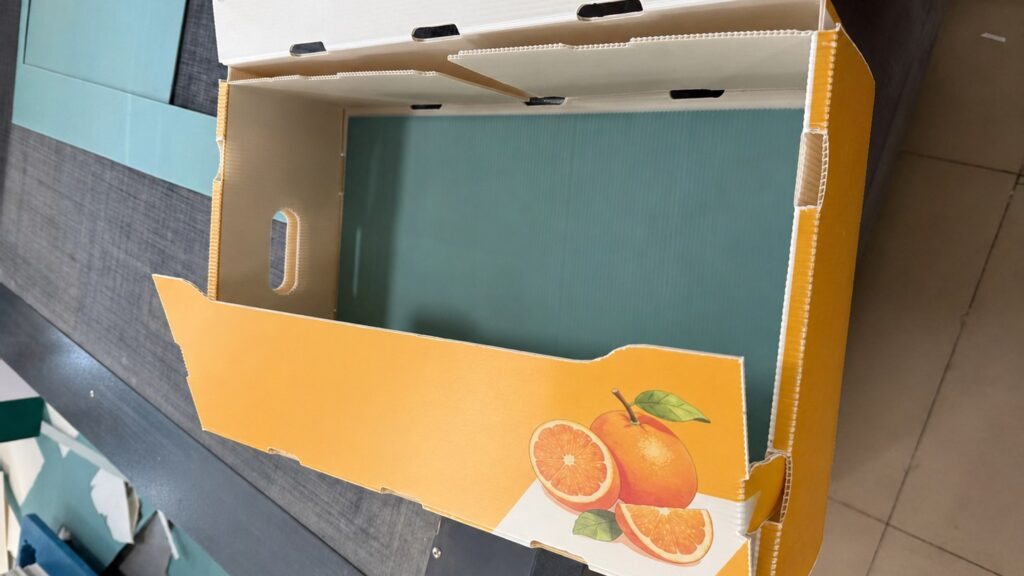
Choose material together with the cell geometry and the support path. A nominal sheet specification cannot replace a fit check or a project-specific load review. Avoid treating any thickness or GSM as a universal “automotive grade.” If an outer PP corrugated box is part of the system, its wall and base structure must also be considered.
Design for Loading and Unloading
Packaging is used by people, not displayed in a static drawing. Allow room for hands or the approved handling tool, confirm the insertion direction and check the order in which parts are removed. The part must not require an awkward twist that brings a sensitive surface against a divider. Grasp points, cell labels and line-side presentation can matter as much as a tight dimensional fit.
Walk through the operator’s sequence. If a cell grips the part so tightly that removal is slow or risky, revise it even if the part appears stable while packed.
Consider Stacking and Transport Loads
Review the weight of the complete loaded container, the number of tiers, the outer box structure and the direction in which load reaches the dunnage. Distinguish palletized transport from floor stacking or line-side accumulation. Vibration, repeated handling and warehouse storage may expose weaknesses that a stationary fit check misses. Where layers are used, make clear whether load is carried by the outer walls, the internal supports or the parts themselves.
Stack height and capacity require project-specific review; sheet thickness alone is insufficient. Record the intended stacking condition so a prototype can be reviewed against it.
Design for the Returnable Handling Route
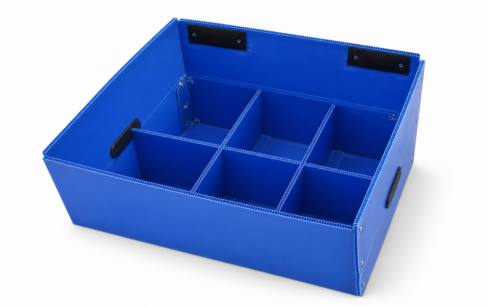
When the pack is intended for repeated use, map the entire route rather than merely choosing a reusable material. Note the number of handling points, storage and transport conditions, cleaning or inspection needs, and how empty packs return. Check whether inserts should be removable or replaceable, and whether the empty unit must nest, fold or stack. These requirements can change the preferred attachment method and the balance between a rigid assembly and a modular one.
The warehouse and returnable logistics application explains the broader route context. For this guide, the key question is how that route affects the actual part-locating structure.
Prototype and Review Before Production
Depending on the project, the design may be reviewed through drawings, a sample structure, trial packing or a prototype before production. Check the actual part fit, approved contact points, loading and unloading access, divider stability and any stated stacking condition. Photograph or record observed interference rather than assuming a drawing has resolved it. Revise slot positions, cell clearance, support placement or outer-container dimensions where the review finds a conflict.
Our automotive parts packaging design case study shows how an RFQ separated outer containers from internal protection and recorded questions still requiring validation. It is a project example, not proof that every design has passed the same tests.
Information Needed for a Dunnage Project
A useful initial brief lets a packaging team distinguish confirmed requirements from assumptions. Send what is available and identify any open items:
- Part drawing or overall dimensions, plus photographs of relevant features
- Part weight and any off-center load or protrusion
- Sensitive surfaces and approved contact points, if known
- Required quantity per container and preferred part orientation
- Existing box or tote dimensions, if the outer container is fixed
- Loading direction, removal sequence and operator access needs
- Stacking requirements, handling route and empty-return conditions
- Estimated order quantity and any drawing or sample approval process
Missing information does not stop an initial discussion, but it should be resolved before a final structure or performance requirement is approved.
Related Automotive Packaging Solutions
The industrial and automotive packaging application describes the broader handling context. For a specific component, compare the roles of custom dunnage, dividers and inserts and the outer PP corrugated box. The automotive packaging case study illustrates an actual RFQ review; it does not establish a universal specification.
Frequently Asked Questions
What information is needed to design automotive dunnage?
Start with part drawings or dimensions, weight, photos, sensitive surfaces, permitted contact points, quantity per container, loading direction and the handling route. Confirm any fixed tote and stacking constraints.
Is thickness or GSM more important for corrugated plastic dunnage?
Both matter, but they describe different properties. Thickness alone does not define structural strength; GSM, formulation, rib geometry, panel dimensions and load direction also influence performance.
Can dunnage fit an existing tote or box?
Often the design can begin with an existing container. Its usable internal dimensions, attachment features, loading access and support path still need checking against the part and required quantity.
What is the difference between dunnage and dividers?
Dividers mainly create separation or cells. Dunnage is the complete locating and protective arrangement, which may include dividers, inserts, pads or supports as components.
Can dunnage be designed for a returnable route?
Yes, when the route is specified. Review repeated handling, inspection, cleaning, empty return and whether internal components should be replaceable; confirm suitability for the actual project.
Discuss Your Automotive Dunnage Project
Send us the part drawing or dimensions, weight, quantity per container, sensitive surfaces and handling requirements. We can review the packaging structure and identify the information needed before quotation.